Battery testers ACK series are a powerful tool for a variety of tests of cells, batteries, supercapacitors, supercapacitor modules, and any other chemical current sources.
Page content
- General information about ACK battery testers
- What do ACK battery testers measure?
- ACK testers modifications
- Main parameters of ACK battery testers
- Battery connection and parallel operation of devices
- Testing program
- Battery test modes
- Equivalent Series Resistance (ESR) measurement
- Measuring of capacitance of supercapacitors
- Measurement result files
- Software
- Autonomous operation of ACK testers
- Certificates
- Ordering ACK battery testers
General information about ACK battery testers
Battery testers ACK series tests various sources and energy storage devices, for example:
- accumulators and rechargeable batteries of any type (Li-ION, Li-Po, LiFePo4, LTO, NMC, Ni-Cd, Ni-MH, Pb-Acid, as well as any others)
- supercapacitors (ultracapacitors), as well as batteries of them
- galvanic cells (primary power supplies)
- fuel cells and also battery of them
- redox batteries
- solar panels
- wind turbines
- as well as any other chemical and physical sources and storages of energy.
Battery testers ACK series contain a controlled power supply and also a controlled electronic load. The power supply can operate in voltage, current or power stabilization modes. The load can operate in voltage, current or power stabilization modes, as well as in resistance stabilization mode.
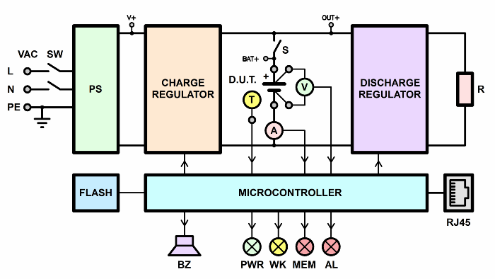
Due to this, battery testers ACK series can provide a wide variety of operating modes. For example, charging, discharging, and cycling charging and discharging the battery. Testing is performed according to a very flexible test program.
Battery testers ACK can perform many tests.
For example, the simplest, such as a single charge or a single discharge of the battery.
In addition, the instruments can perform cyclic tests, with multiple alternation of charge and discharge. This is relevant for resource and climatic tests of batteries.
Finally, battery testers ACK series can perform complex combination modes that simulate real-life battery conditions. For example, simulating the operation of an electric car battery when a car is moving in an urban driving cycle.
What do battery testers ACK measure?
During the tests, the ACK battery testers measure::
- battery charge capacity in Ah;
- battery energy capacity in Wh;
- equivalent series resistance of the battery (ESR) in Ohms;
- electric capacity of supercapacitors in Farads;
- efficiency of the charge discharge cycle in terms of capacity (by Ah) in %;
- efficiency of the discharge charge cycle in terms of energy (by Wh) in %;
- and also, average leakage current per cycle in A.
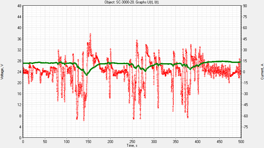
The tester returns measurement results of the parameters of the tested battery in the form of text result files. In addition, software of device automatic plotts of charts of the charge discharge of the tested battery. Finally, software of tester automatically builds graphs of degradation of battery parameters (which is convenient, for example, during cycle-life tests).
Modifications of battery testers ACK
Battery testers ACK are available in several modifications:
These modifications differ in the following characteristics:
- operating range of charge and discharge current
- operating voltage range
- and also, the maximum power that the tester can give when charging and receive when discharging.
The rest of the testers of various modifications are identical to each other.
The main parameters of the battery testers АCК
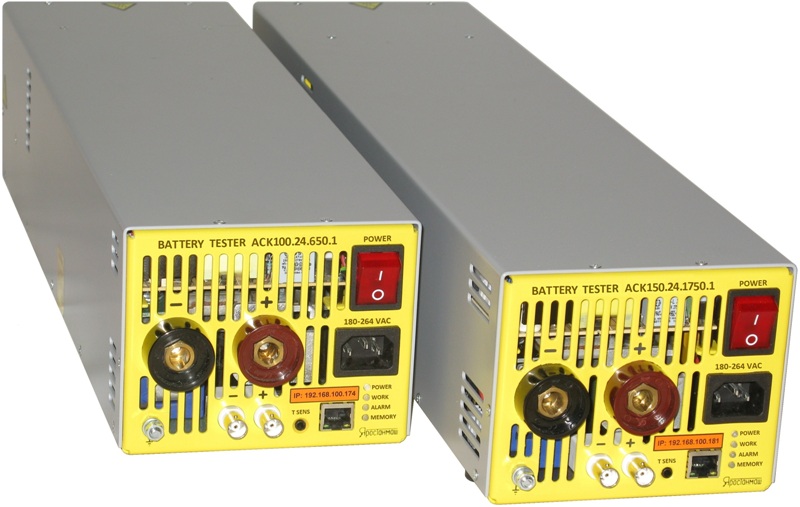
ACK150.24.1750.1
- Charge current, as well as discharge current: from 1 to 150 A (up to 3000 A with parallel operation of devices);
- Battery voltage operating range: from 1 to 28 V;
- Maximum charge power, as well as discharge power: 1750 W (up to 35 kW with parallel operation of devices);
- Dimensions (height x width x length): 120 x 140 x 540 mm;
- Device weight: 10.4 kg (22 lbs).
ACK75.48.1750.1
- Charge current, as well as discharge current: from 0.5 to 75 A (up to 1500 A with parallel operation of devices);
- Battery voltage operating range: from 1 to 56 V;
- Maximum charge power, as well as discharge power: 1750 W (up to 35 kW with parallel operation of devices);
- Dimensions (height x width x length): 120 x 140 x 540 mm;
- Device weight: 10.4 kg (22 lbs).
ACK100.24.650.1
- Charge current, as well as discharge current: from 1 to 100 A (up to 2000 A with parallel operation of devices);
- Battery voltage operating range: from 1 to 28 V;
- Maximum charge power, as well as discharge power: 650 W (up to 13 kW with parallel operation of devices);
- Dimensions (height x width x length): 120 x 140 x 460 mm;
- Device weight: 8.1 kg (18 lbs).
ACK50.48.650.1
- Charge current, as well as discharge current: from 0.5 to 50 A (up to 1000 A with parallel operation of devices);
- Battery voltage operating range: from1 to 56 V;
- Maximum charge power, as well as discharge power: 650 W (up to 13 kW with parallel operation of devices);
- Dimensions (height x width x length): 120 x 140 x 460 mm;
- Device weight: 8.1 kg (18 lbs).
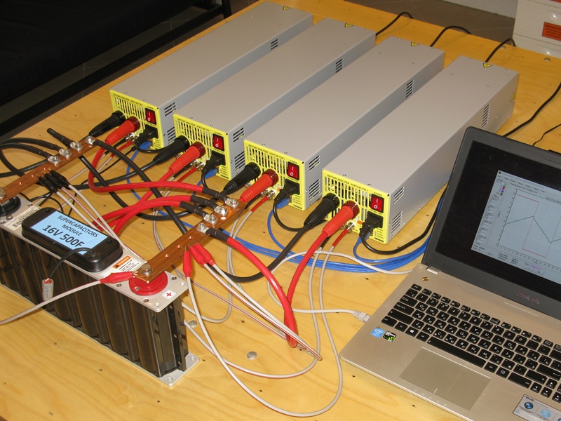
Connecting the battery to the ACK battery tester and parallel operation of the testers
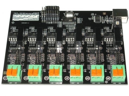
The battery is connected to the device using a four-wire circuit. Two power conductors as well as two low current conductors help to do this. This connection scheme allows you to monitor the voltage directly at the terminals of the tested battery.
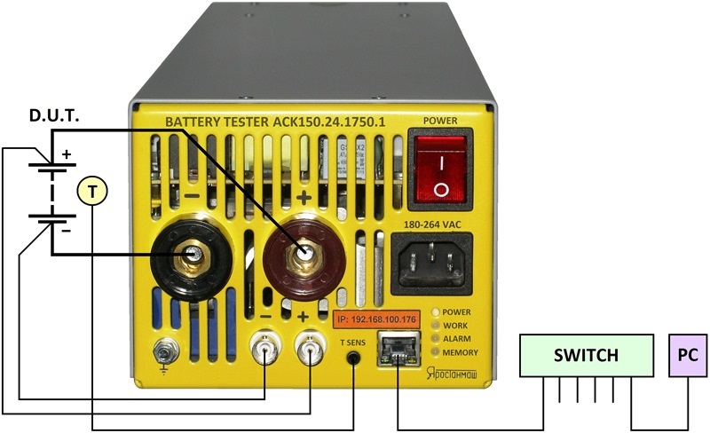
In addition, each device has an external battery temperature sensor. Temperature sensor readings can be used for protective functions during testing. In particular, for the protection against overheating of the tested battery. Also, the temperature sensor helps to carry out climatic tests. In the course of climatic tests, software of tester builds graphs of the dependencies of the battery parameters on its temperature.
If the current or power of one device is not enough, the ACK testers can work in parallel. The charge current and power, as well as the discharge current and power, increase in proportion to the number of devices.
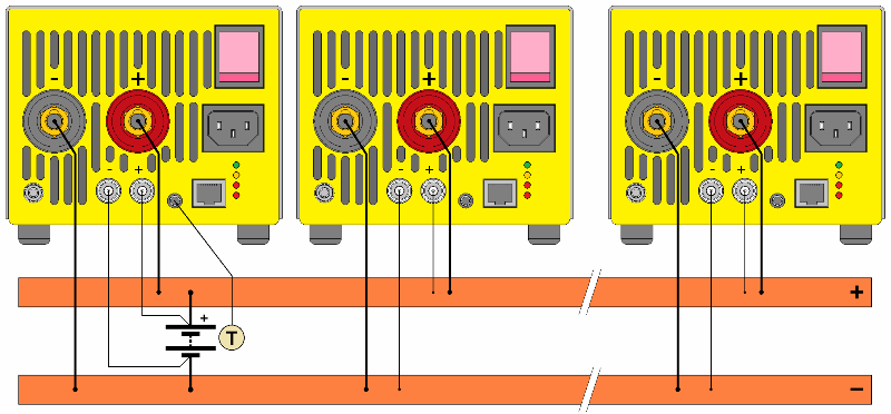
For example, when four ACK150.24.1750.1 testers work in parallel, you can get a charge and discharge current of 600 A. Also and the maximum charge and discharge power can reach 7 kW.
Battery testing program on the battery testers ACK
Battery testing on the ACK tester performs according to a user-configurable test program. The test program has very flexible settings. The user configures the test program before starting the test.
The battery test program may contain:
- up to three test preparation steps performed once;
- up to 42 steps in the cyclic part of the program, executed a given number of times;
- as well as up to 3 steps of completion of the test, performed once before the end of the test.
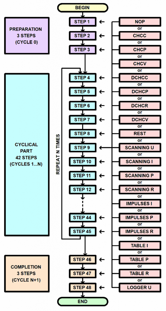
At each step of the testing program, the ACK battery tester can provide the following operating modes:
- Charge with constant current;
- Discharge with constant current;
- Charge with constant power;
- Discharge with constant power;
- Charge at constant voltage;
- Discharge at constant voltage;
- Discharge at constant resistance;
- Voltage scanning;
- Current scanning;
- Rest;
- Power scanning;
- Resistance scanning;
- Current pulse mode;
- Power pulse mode;
- Resistance pulse mode;
- Current table mode;
- Power table mode;
- Resistance table mode;
- as well as voltage logger mode.
You can configure the repeating of the cyclic part of the testing program over a million times. Therefore, battery testers ACK suitable for supercapacitors cycle-life tests.
Battery test modes on the ACK tester
ACK battery testers can provide multiple modes of operation with the battery under test. Their variety is large enough.
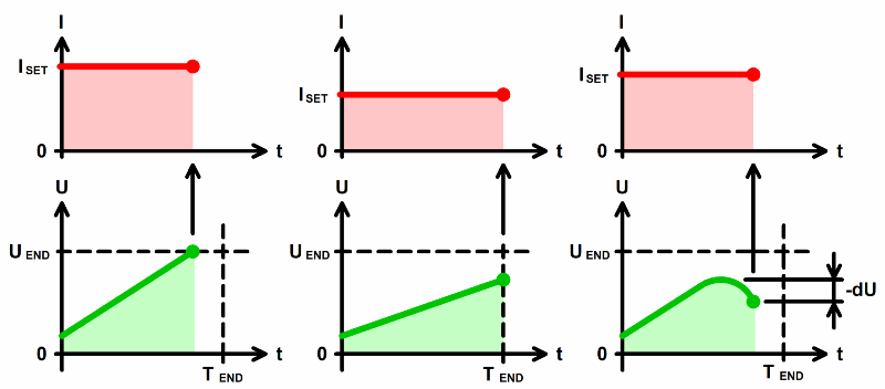
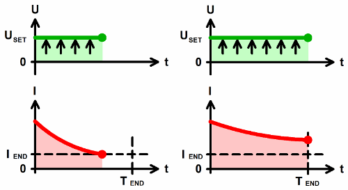
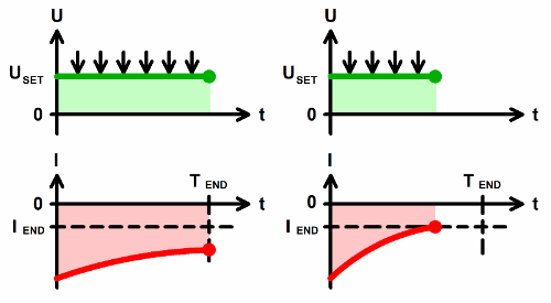
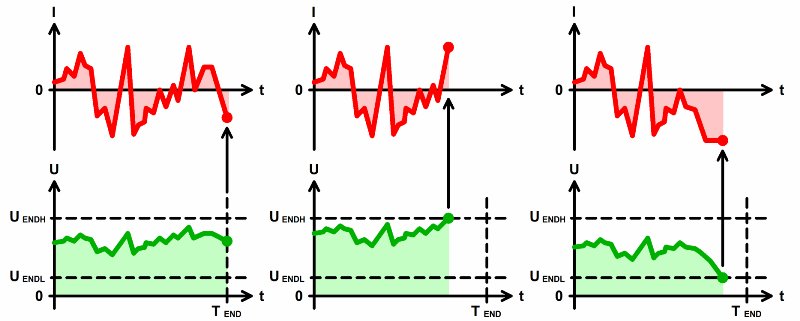
Charge with constant current
designed to maintain a given charge current regardless of voltage changes. Despite the increase in battery voltage, the charge current remains constant and equal to the specified current.
The step ends in the following cases:
- when the voltage reaches a predetermined threshold
- after the specified step time has elapsed
- as well as if the voltage starts to decrease.
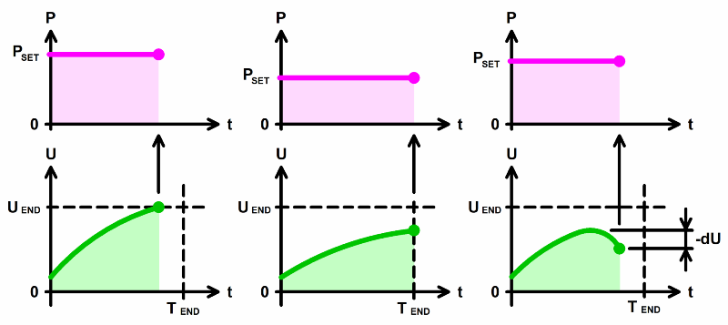
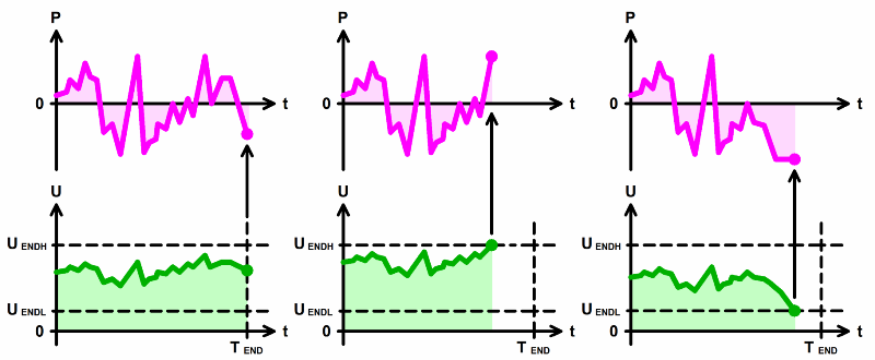
Charge with constant power
maintains a given charge power on the battery. As the voltage rises, the charge current will decrease in order to keep the power value at a given level.
Charge at constant voltage
designed to keep the voltage on the battery at a given level after the main charge. The step, for example, helps to complete a two-stage charge in CC – CV mode. The end of the step occurs when the current drops to a predetermined value, as well as after a predetermined time.
Discharge at constannt current
designed to maintain a given discharge current regardless of voltage. Despite the decrease in voltage, the discharge current remains constant and equal to the specified.
The end of a step occurs when the voltage decreases to a specified value, or after a specified time.
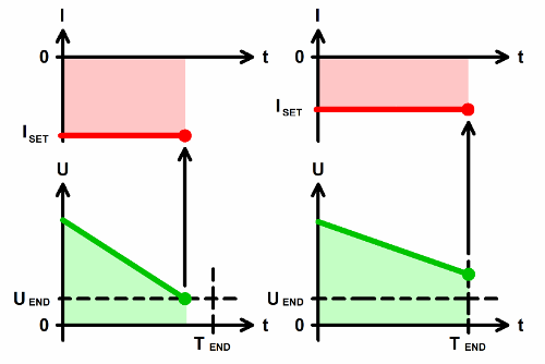
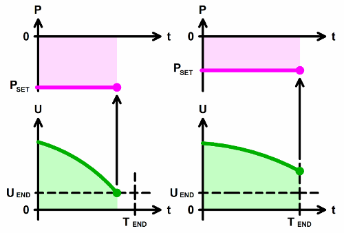
Discharge with constant power
designed to maintain the specified discharge power. As the voltage decreases, the current will increase, so the battery discharge power will remain at the specified level.
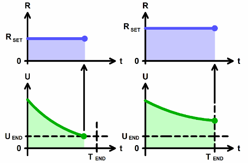
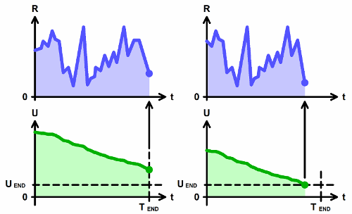
Discharge at constant resistance
designed to maintain a given battery discharge resistance. With a decrease in voltage, the current will also decrease so that the ratio of voltage and current is equal to the specified.
Discharge at constant voltage
designed to hold the voltage at a given level after discharge. In this mode, the device simulates a powerful zener diode with a given stabilization voltage.
The end of the step occurs when the current drops to a predetermined value, as well as after a predetermined time.
Rest mode
is a pause in the test. In rest mode, the device interrupts the current flow through the battery for a specified time.
Voltage scanning mode
smoothly changes the voltage on the battery. The voltage changes from a given start value U1 to a given end value U2 at a given rate.
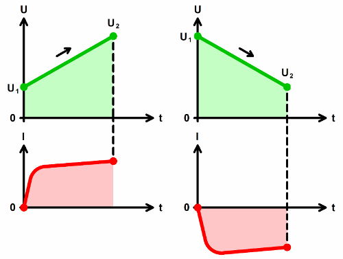
You can use a combination of the two voltage scanning modes in the cyclic part of the test program. This makes it possible to investigate chemical current sources by the method of cyclic voltammetry in the mode of a powerful potentiostat galvanostat.
Current scanning mode
smoothly changes the current through the battery. The current changes from the set start current I1 to the set end current I2 at a given speed.
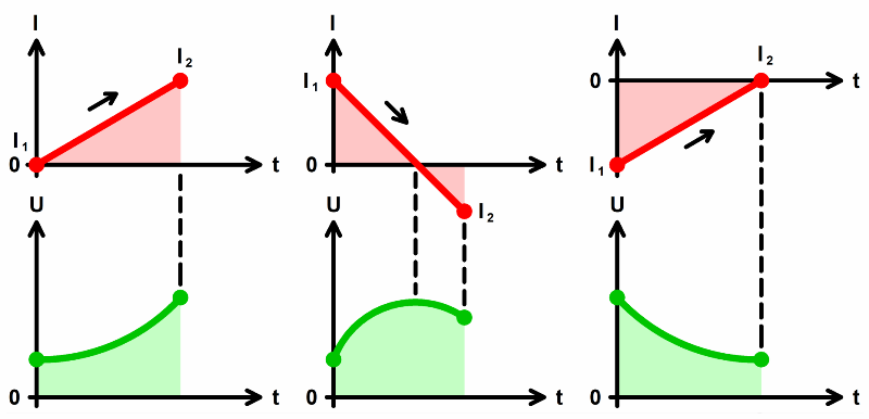
The currents I1 and I2 can be either positive (charge current) or negative (discharge current). In addition, one of the current values can be zero.
Power scanning mode
smoothly changes the power on the battery. The power changes from a given initial power P1 to a given final power P2 at a given speed.
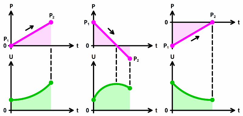
The powers P1 and P2 can be either positive (charge power) or negative (discharge power). In addition, one of the power values can be zero.
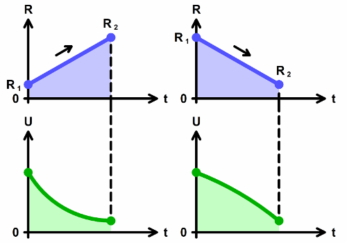
Resistance scanning mode
smoothly changes the load resistance for the battery. The resistance changes from the initial value R1 to the final value R2 at a given speed.
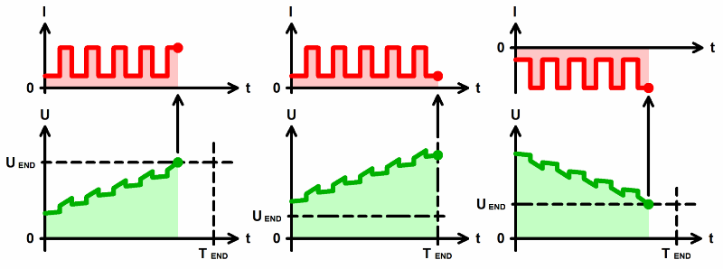
Current pulse mode
supplies alternating current pulses of set values I1 and I2 through the accumulator. The current I1 applies for the set time T1, while the current I2 applies for the set time T2.
The currents I1 and I2 can be either positive (charge current) or negative (discharge current).
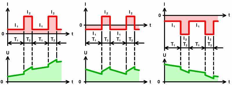
The step ends when the battery voltage reaches the specified value, as well as after the specified time.
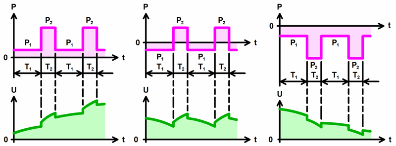
Power pulses mode
supplies alternating power pulses with preset values P1 and P2 to the battery. Power P1 applies for a given time T1, while power P2 applies for a given time T2.
The powers P1 and P2 can be either positive (charge power) or negative (discharge power).
Resistance puls mode
supplies alternating impulses of resistance of preset values R1 and R2 to the battery. Resistance R1 applies for a given time T1, while resistance R2 applies for a given time T2.
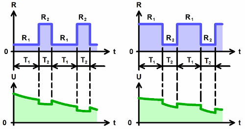
Table modes
A separate class of operating modes for testers of batteries is work according to the tables of current, power and resistance. In these modes, the battery tester operates according to previously prepared and selected tables. Tables must contain two columns. The first column is time. The second is the required values of current (power or resistance), which should be at this time.
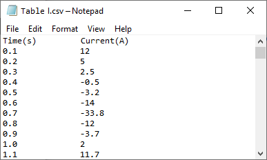
The table modes simulate battery performance in a wide variety of applications. For example, simulating the operation of an electric car battery when the car is moving in an urban driving cycle, or in any other.
The table modes will be useful for simulating the operation of batteries, for example, in:
- electric transport
- solar stations
- wind farms
- wave generators
- tidal power plants
- as well as in any systems where the change in current, power or resistance of the load on the battery occurs according to complex paterns.
Current table mode
allows you to pass a current of a given value, direction and shape through the battery. The current supplies according to the specified current table.
The step ends at the end of the specified table. In addition, the step ends when the battery voltage reaches the specified lower or specified upper thresholds.
Power table mode
allows you to supply the battery with the power of a given value, direction and shape. Power supplies according to the specified power table.
Resistance table mode
allows you to apply a load resistance of a given value and shape to the battery. Surely, resistance applys according to the specified resistance table.
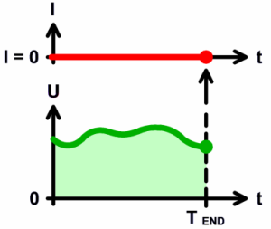
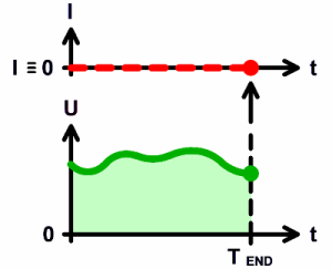
Voltage logger mode
on the battery terminals allows you to record changes in voltage over time. In logger mode, the power circuits of tester disconnects from the battery. This provides a high input impedance of the device and, therefore, a small effect on the battery under test.
The logger mode ends after the specified time.
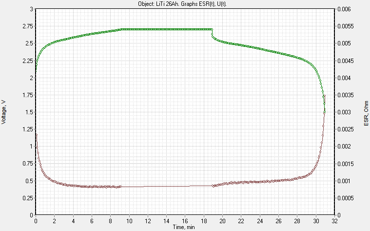
Measurement of the equivalent series resistance of the battery
ACK battery testers are capable of measuring battery equivalent series resistance (ESR).
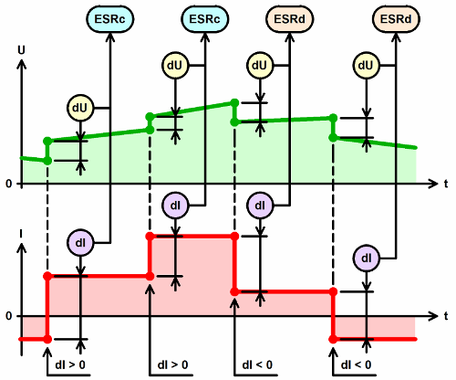
There are few ways for ESR measurement. The most accurate way is to interrupt the charge and discharge current with a specified period for a specified time.
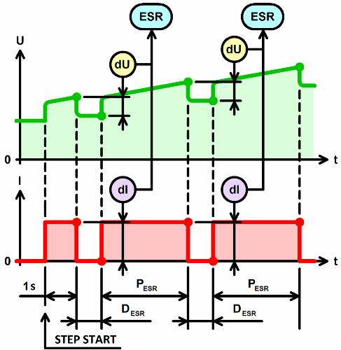
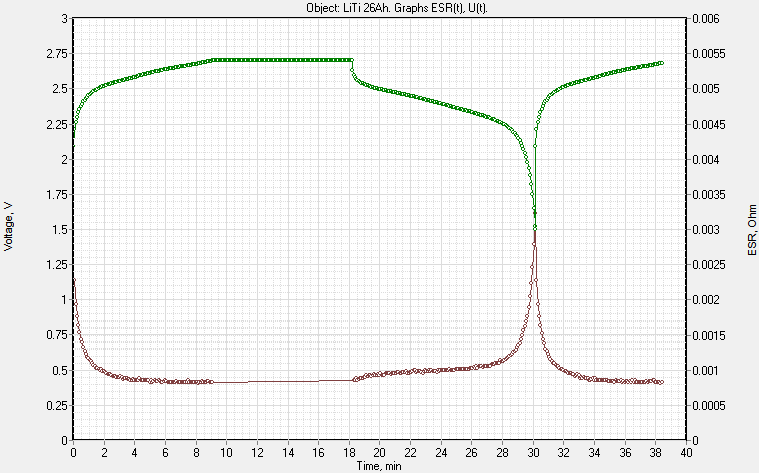
This measurement mode allows you to plot the dependence of the ESR of the battery on the degree of its charge or discharge.
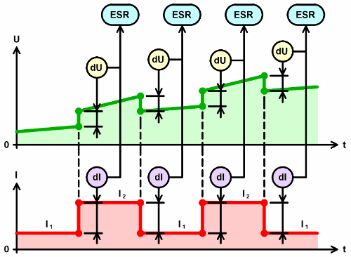
ESR measurement also occurs when changing pulses of current, power or resistance in the pulse modes.
In addition, ESR measurement takes place when changing steps in the testing program.
Measuring of capacitance of supercapacitors
Among other things, ACK testers are capable of measuring the electrical capacitance of supercapacitors, in Farads. The capacitance is measured at the constant current discharge step.
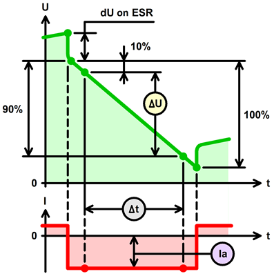
C = Ia x Δt / ΔU
Measurement result files
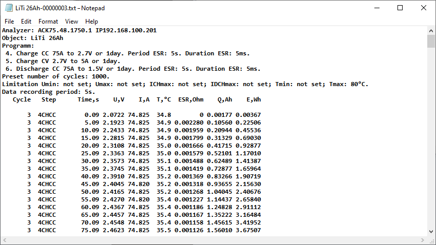
The end result of the work of the ACK battery testers are text files of the measurement results. The tester stores two types of result files. Several files of primary data, as well as one general file of summary measurement results.
Primary data files are saved one for each charge discharge cycle performed. If the test program requires a large number of charge-discharge cycles, you can customize results files thinning. In this case, the primary data files will be saved, for example, only for every 10th cycle.
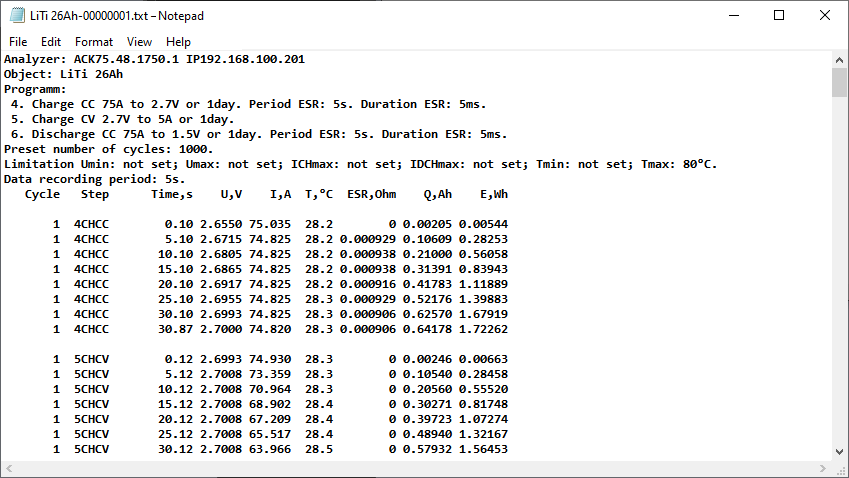
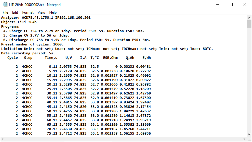
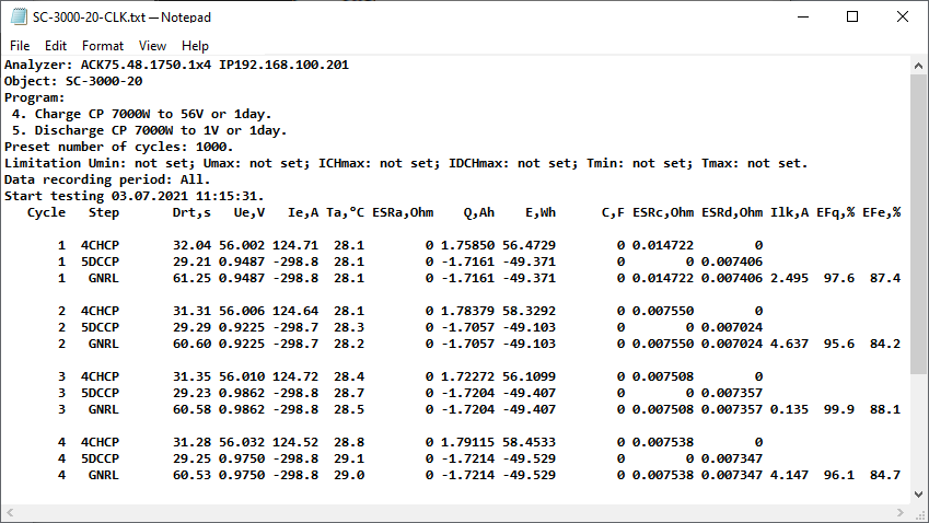
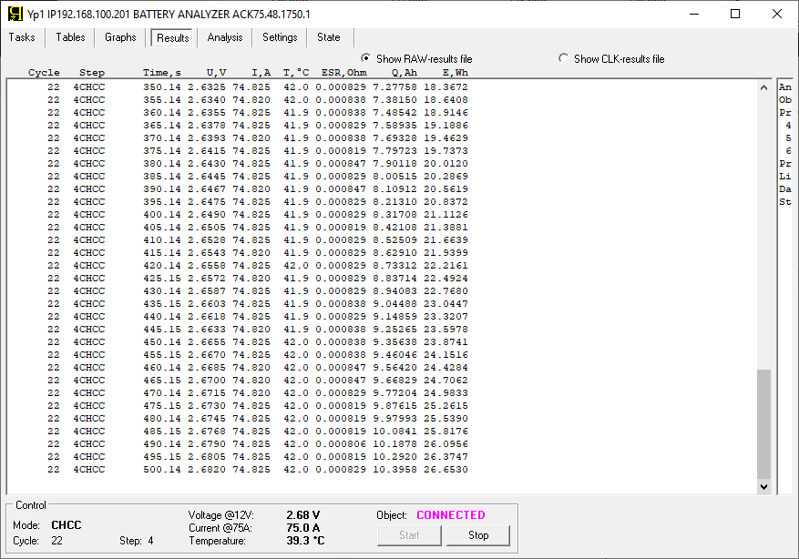
Primary data files
contain the following parameters:
- instantaneous values of voltage (V), current (A) and temperature (°C of °F) with a given step of fixing parameters in time
- instantaneous ESR values measured during charge or discharge, Ohm
- given or received capacity, Ah, cumulative from the beginning of the step
- as well as the given or received energy, Wh, cumulative from the beginning of the step.
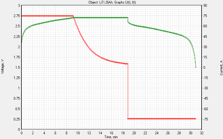
Based on the measurement results from the primary data files, there can be:
- built charge discharge graphs of the battery
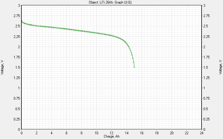
- determined the capacity and energy stored by the battery in a specific voltage range
- built graphs of cyclic voltammetry
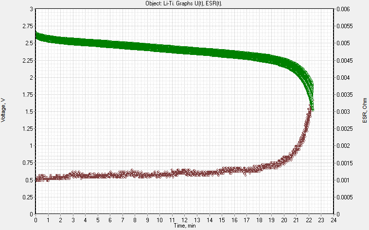
- built graphs of ESR changes during charge and discharge
- and also built graphs of voltage, current, temperature, capacity, energy and ESR in various combinations.
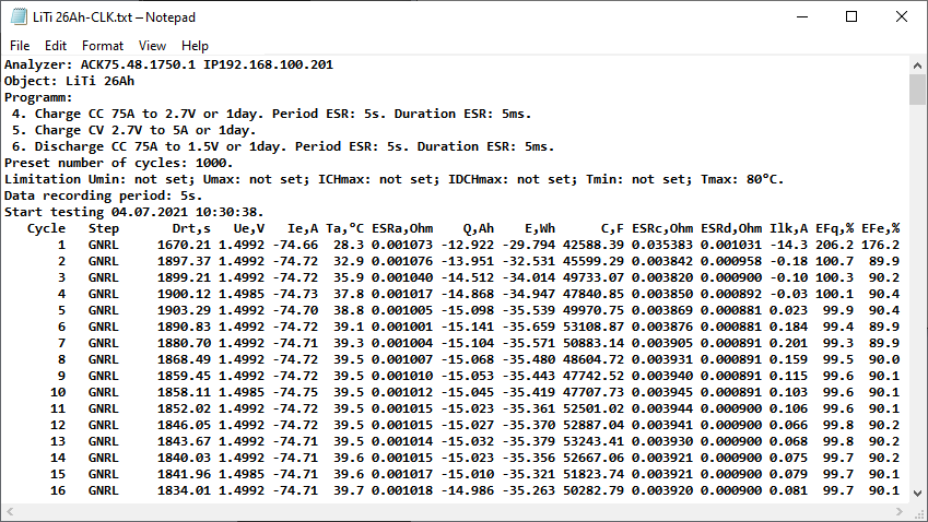
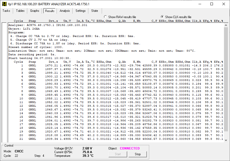
Summary measurement result files
contain processed data. Each line of the summary results file describes summary data for a whole step, or for a whole cycle.
The lines of the summary measurement results file contain
- full duration of a step or cycle
- final voltage on the battery, V
- final current, A
- average battery temperature per step or per cycle, °С or °F
- average ESR per step or per cycle, Ohm
- total returned capacity, Ah
- total returned energy, Wh
- measured capacitance in Farads
- ESR values measured at the beginning of the charge, as well as at the beginning of the discharge, Ohm
- average leakage current per cycle, A
- as well as the efficiency of the battery in terms of charge and in terms of energy, %
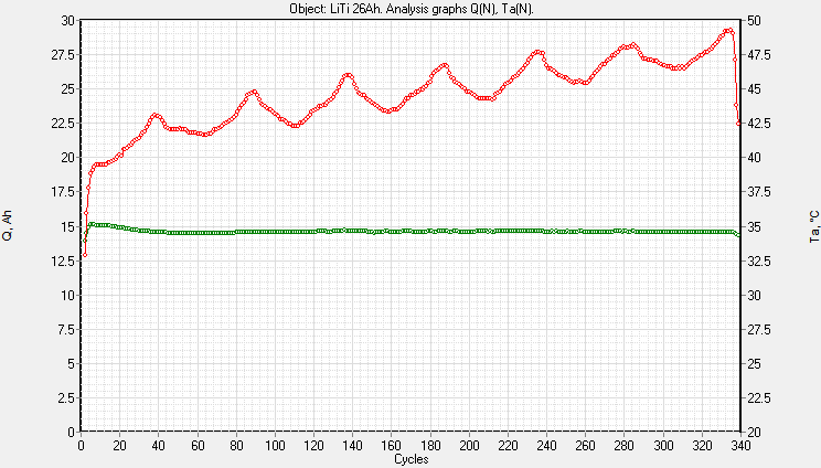
The software can generate the following types of graphs based on the summary measurement results:
- graphs of changes in battery parameters depending on the number of charge discharge cycles passed
- graphs of changes in battery parameters depending on its temperature.
This is very useful, for example, for cycle-life testing of batteries or climatic testing of batteries.
Software for battery testers ACK
Battery testers work in connection with special software for user’s computer – Computer Interface Yp1. User should install this software on his computer.
The Yp1 software is versatile. It is suitable for working with all modifications of devices (ACK150.24.1750.1, ACK75.48.1750.1, ACK100.24.650.1 and ACK50.48.650.1). We supply the software with the testers.
The Yp1 software contains several pages. These pages help to:
- preparing and launching a testing program
- monitoring the progress of tests
- receiving and saving measurement results
- tester monitoring
- as well as identifying the reasons for the abnormal termination of testing in case of its occurrence.
“Tasks” page
allows you to set up the testing program.
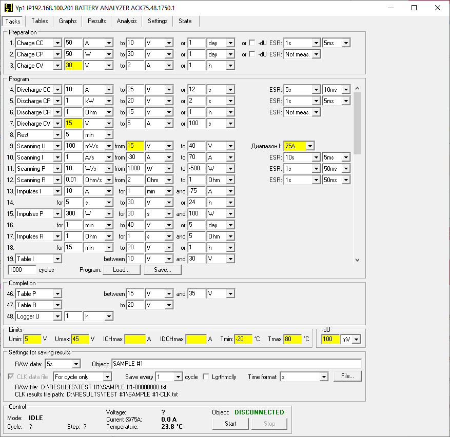
On the “Tasks” page you should:
- select and configure the test mode for each step of the test program
- introduce protective levels of voltage, current and temperature
- select the required modes of saving data to measurement results files
- enter battery name
- select the path to the measurement results files
- run the test with the “Start” button
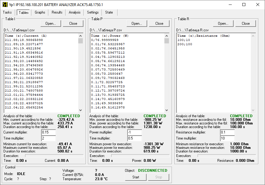
“Tables” page
iis intended for selection and adjustment of tables for operating modes according to tables. Here you can select the individual table files for the operating modes according to the current, power and resistance tables. The user can quickly adjust the time range, as well as the range of the parameter in the table with the required multipliers.
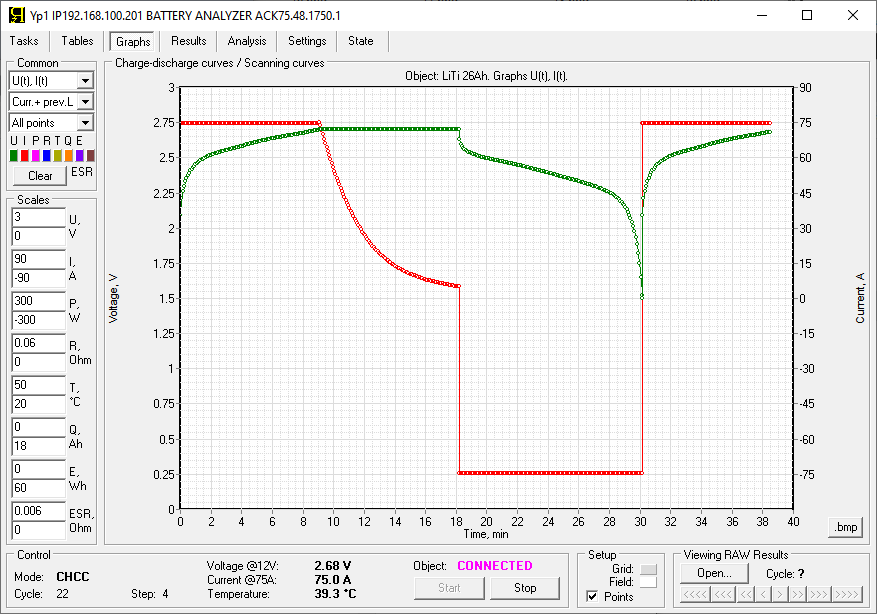
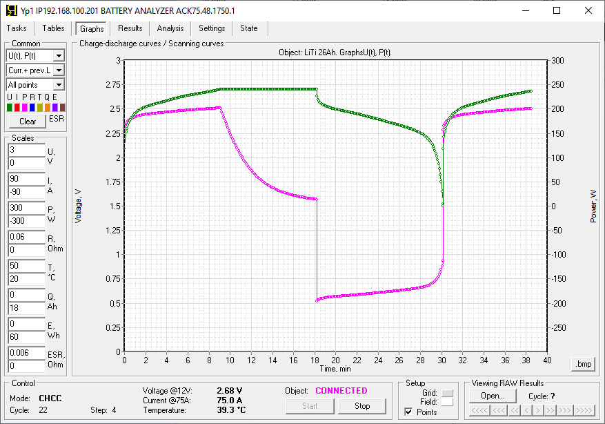
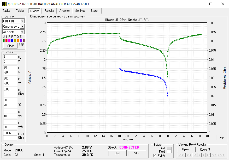
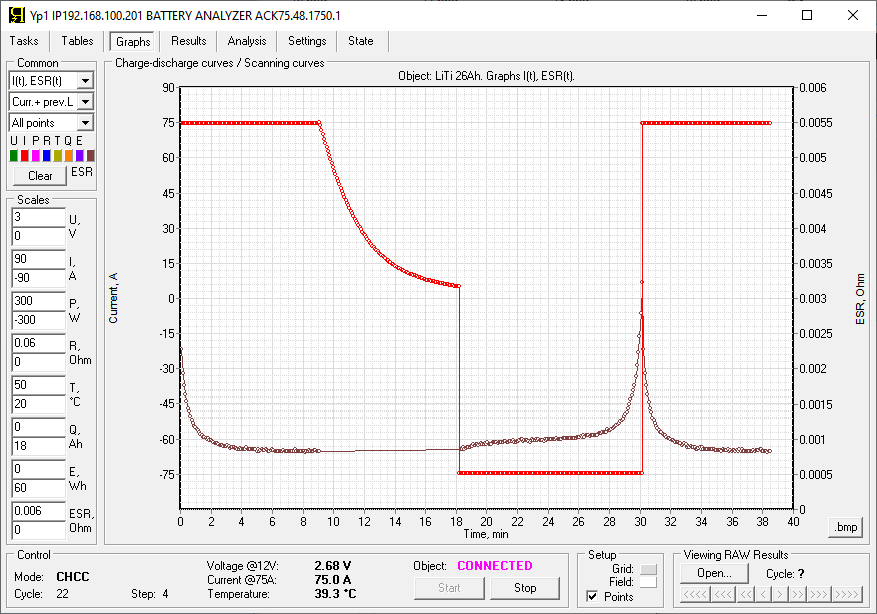
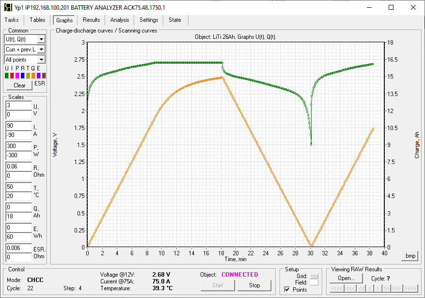
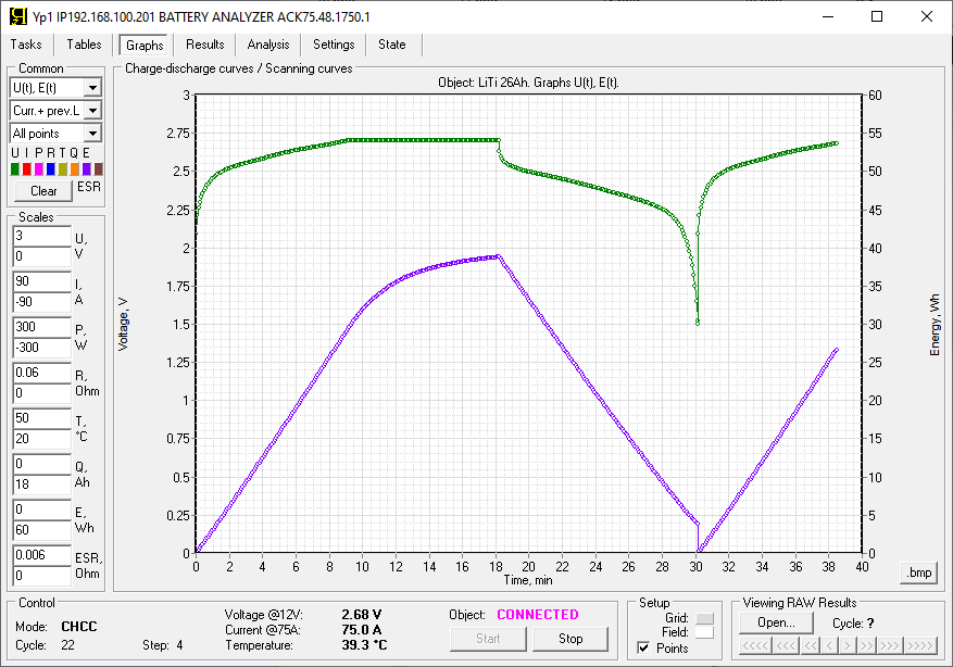
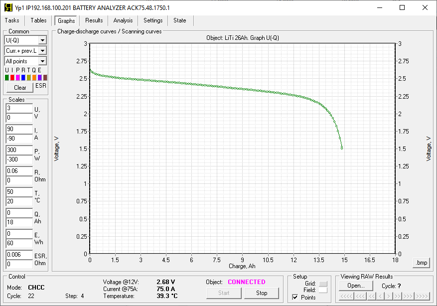
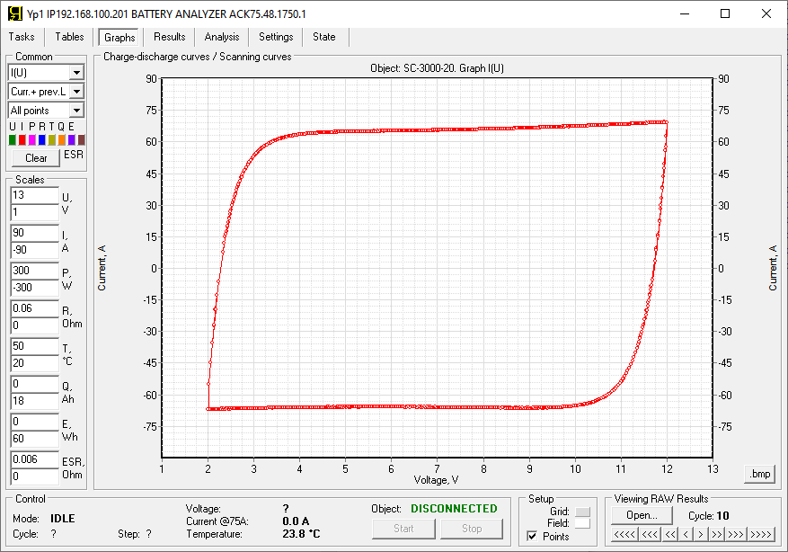
“Graphs” page
displays the graphs of the charge discharge of tested battery. Here you can see changing parameters of battery in various combinations, for example:
- voltage and current
- power and voltage
- voltage and load resistance
- ESR and voltage
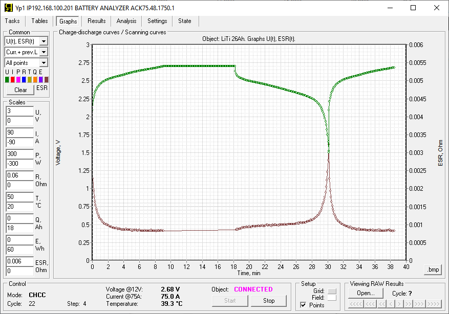
- current and ESR
- voltage and charge
- voltage and energy
as well as special display modes, for example:
- dependence of voltage on the given charge
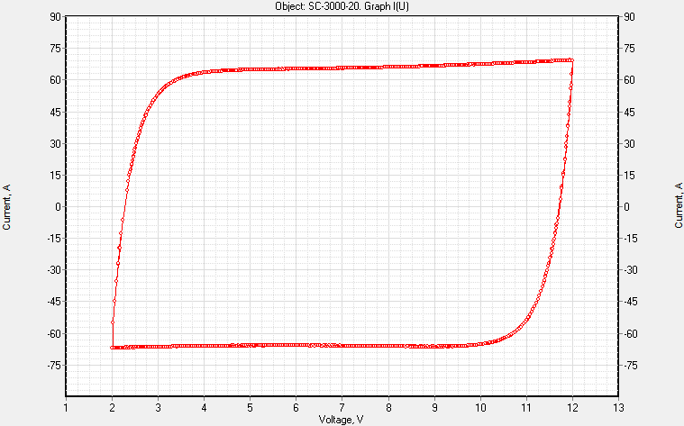
- dependence of current vs voltage, which is convenient when testing a sample by the method of cyclic voltammetry
“Results” page
allows you to observe the formation of files of measurement results.
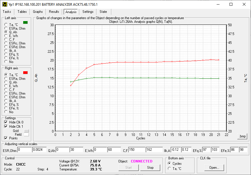
“Analysis” page
displays graphs of changes in battery characteristics depending on the following parameters:
- from the number of completed charge discharge cycles
- depending on battery temperature
The page allows you to visually observe the change in the characteristics of the battery during cycle-life tests, as well as during climatic tests.
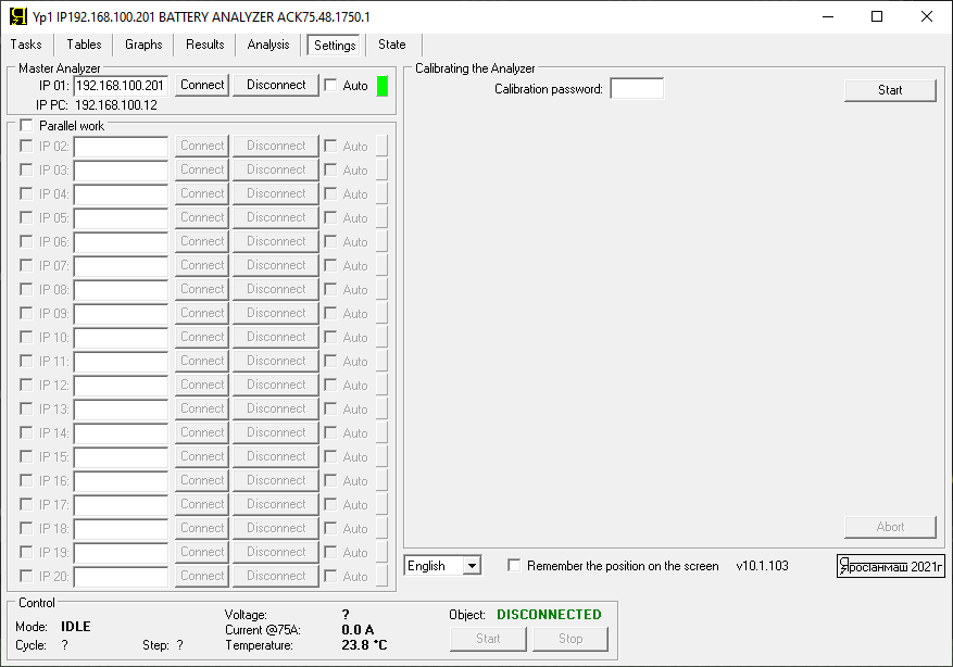
“Settings” page
is intended for setting up a connection to a battery tester or to several testers in their parallel operation.
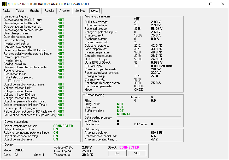
“Status” page
provides detailed information on the operation of the ACK battery tester. In addition, information is provided on various emergency events that may occur during the tests.
Among other things, the Yp1 software allows you to open and view results files obtained in the past. After opening the files, the software automatic plots of the charge discharge charts, as well as degradation charts. Viewing historical files is possible, including in the Off-line mode, without connecting to the device.
Autonomous operation of battery testers АСК
The ACK battery testers have built-in memory. The memory halps to save the measurement results in case the connection with the computer becomes temporarily unavailable.
When the connection is restored, the tester transfers all the accumulated data to the computer. Then the Yp1 software saves the data to the files of the measurement results.
As a result, the built-in memory enables the battery tester to operate autonomously for some time after starting the test. This allows you to turn off your computer at night, as well as on weekends or holidays.
| Data save period | Estimated maximum autonomously period |
| “All” | 4 hours |
| 0.1 s | 7 hours 30 minutes |
| 0.2 s | 15 hours |
| 0.5 s | 1.5 days |
| 1 s | 3 days |
| 2 s | 6 days |
| 5 s | 15 days |
| 10 s | 1 month |
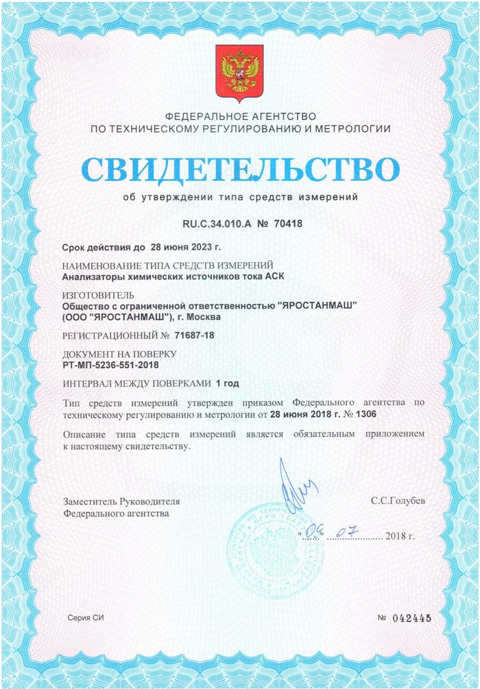
Certificates
Ordering battery testers
To order ACK battery testers, call us by phone
- +7(495)997-04-66
- +7(926)531-17-63
- +7(926)590-71-52
or send a request to the email address Yarstst@gmail.com
We supply battery testers under a supply contract.
The cost, as well as the delivery time, depends on the required number of devices.